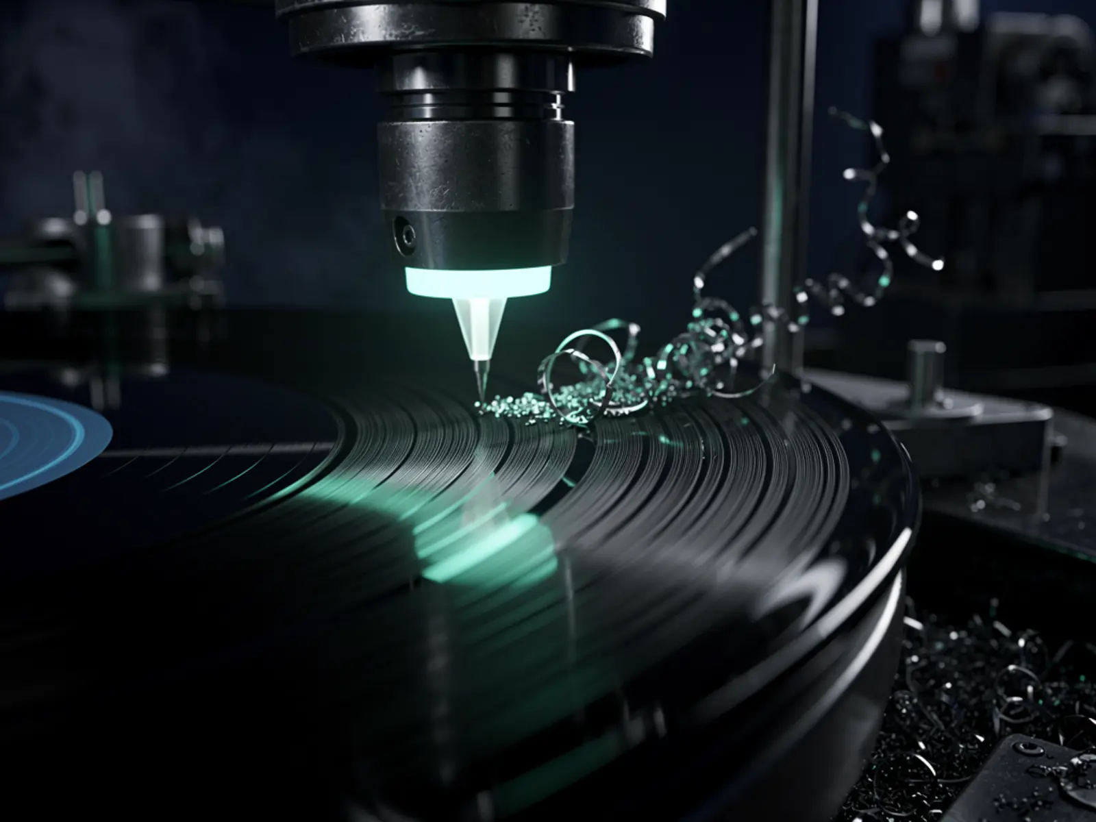
The idea
Produce a short, replayable mono test groove and characterise its limitations. V1 is a controlled audio/mechanical experiment, not a claim of commercial vinyl mastering quality. Specify the blank material and whether the process cuts or embosses; those require different tooling and setup.
The connection
Audio, precision motion and material behaviour meet at a tiny moving contact. The appeal is making the recording process visible and building an instrument for physical sound.
How it could work
Separate platter speed, radial feed, cutting-head mechanics and audio drive. Use a known stable platter as a baseline where possible. The head's force, damping, stylus geometry and thermal limits matter as much as its amplifier. A printed holder can support experiments but does not establish the stiffness or frequency response of a successful cutter head.
Start with low-level mono tones and a conservative, documented setup appropriate to the chosen head and blank. Avoid a first milestone that requires stereo groove geometry or an uncharacterised heated stylus. Provide guarded motion, a rapid lift and a safe way to remove swarf if the process produces it.
What would prove it
Validate platter speed and carriage feed without contacting a blank. Then create a short test containing silence and a modest mono tone using a compatible head/stylus procedure. Replay it with a known pickup and record the result. Compare recorded tone frequency, surface noise and evidence of groove collisions or mistracking.
Proposed gate: feed stays within ±5% of its selected value; three short test grooves replay without skipping on the reference player; starts/stops lift cleanly; the head remains within its documented ratings. Measure frequency response and noise before attempting music or describing the output as high fidelity.
The path to a complete build
- Select cutting versus embossing and source compatible head, stylus and blanks.
- Verify platter speed and carriage repeatability independently.
- Implement lift, limits and protected audio drive.
- Record short test grooves and inspect them before extending duration.
- Publish mechanical drawings, setup conditions, recordings, blank material and test failures together.
Open the engineering notebook
Components, interfaces and calculations
BOM categories are stable platter/spindle, radial carriage and leadscrew, controlled feed motor, supported cutter/embossing head, compatible stylus/blanks, amplifier with suitable protection, measurement pickup and audio interface. Add a microscope or close inspection camera and a speed measurement method.
For pitch p millimetres per revolution, radial feed in mm/min = p × rpm. For usable radial travel Δr, time in minutes = Δr / (p × rpm), before lead-in/out allowances. Example: 30 mm travel at 0.15 mm/revolution and 33⅓ rpm gives about six minutes. This is geometry only; groove excursion, material and tracking constraints may require more spacing.
Scope and development questions
Allow 8–12 experimental sessions after compatible tooling is obtained. The head/stylus/blank system is the main procurement uncertainty; obtain a supplier specification and quote before fabricating the machine around it. Resolve acceptable sound quality and whether this is an art object or a repeatable small-batch process. Audio equalisation and head compensation remain detailed design tasks requiring the chosen system's documentation.
Reference basis
No cutter-head manufacturer specification has yet been supplied or verified for this build. The calculations and experimental gates above are proposed engineering work, not evidence of an existing APX lathe. Selecting and documenting a compatible head/stylus/blank system is the first research gate.